SE-2200, SE-2800, SE-2850 Audio Workflow Guide
Nov 03 2020
|
General Information
SE-2200, SE-2800, SE-2850 Audio Workflow Guide
The audio inputs and outputs on the 2200, 2800, and 2850 series switchers allow you to either:
-
Extract embedded audio from your camera or media player and combine it with your analog audio board mix before re-embedding it tor your switcher's SDI output
- Bypass the analog audio board entirely and pass through the embedded audio sources to your switcher's SDI output
Below are the two basic workflows:
With An Audio Mixer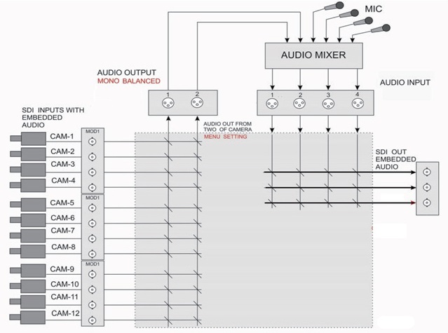 2200/2800
Sources w/ Embedded Audio Switcher SDI inputs Switcher XLR Outputs
Analog Mixer Line Inputs Analog Mixer Line Outputs Switcher XLR Inputs
Switcher SDI Outputs w/ Embedded Audio
This workflow allows you to de-embed audio from your input sources, mix that line level signal with your analog audio sources in an external audio mixer, then return it to the switcher and re-embed it for your video outputs.
For example, with four XLR inputs on your switcher, you can send your main mix to your SDI video recorder on embedded audio tracks 1&2, and also send an additional stereo mix from a mixer bus (for example, without music cues for copyright reasons) to your recorder on tracks 3&4.
Without An Audio Mixer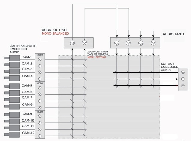 Sources w/ Embedded Audio Switcher SDI inputs Switcher XLR Outputs Switcher XLR Inputs 1&2 Switcher SDI Outputs w/ Embedded Audio
This workflow allows you to pass through embedded audio from your input sources to your video outputs.
For example, if all of your microphones are connected to cameras and you are using embedded audio with your clip players, you can send all of the audio to your SDI video recorder on embedded audio tracks 1&2 by creating a loop with the XLR analog outputs and XLR analog inputs 1&2.
Please note that the 2850 series allows you to also bypass the XLR outputs and inputs with a "virtual patch cable" via the following menu setting:
Menu Audio Tract Audio Pass Through On
Audio Associations
On the switcher keyboard panel, you may notice a button that says Fix | A+V. On the multi-view screen, you will notice along the center that there are either the words Audio Fixed or Audio F Video.
- Audio Fixed enables Audio Associations
- Audio Follows Video bypasses Audio Associations
This means if channel 1 is on Program, any embedded audio contained in that input source (camera, media player, etc.) with output via XLR (or pass-through to the SDI output on the 2850 if enabled).
If you switch to channel 2, it's now extracting audio from that source, as it is following from 1 to 2. This means you can only extract audio from one embedded source at a time.
With default settings and associations, Audio Fixed is the same as Audio Follows Video until you configure it.
So if you configure the audio associations for both channels 1 and 2 to associate with channel 1, when channel 1 or 2 is on program, you will only extract the audio from channel 1, so long as you are in Audio Fixed mode. Audio Follows Video will ignore this change.
Now, if you switch to channel 3, it will extract from channel 3 regardless of the audio mode, because it is still configured with its default association.
Another Example: You have a studio show with 3 cameras on set and a 4th remote camera live in the field. Your audio associations can be either:
-
Audio Fixed: Inputs 1-4 (all cams) take the audio from input 4 (remote cam) and send it to the analog audio mixer for the sound operator to control it's level in the mix.
- Audio Follows Video: Remote audio is only enabled when cam 4 is selected, and the associations are bypassed
To summarize, the default audio associations are matched to their respective inputs, which is functionally the same as audio follows video. Only in changing the audio associations is there a difference between the two modes.
On the 2200 and 2800, you can change the associations in the menu:
2200: Menu Audio Setting Audio Association Input Channel # Value #
2800: Menu Audio Associations Input Channel # Value #
On the 2850, you can change the associations using the Audio XPT button on the keyboard panel:
- Press and hold Audio XPT
- The Program row will light up
- Select the channel you want to edit via the Program row
- The channel it's currently associated with will flash on the Preview row
- Press the channel on the Preview row you want to change the association to
- Repeat steps 3 through 5 until you are done changing associations, and let go of the Audio XPT button
Regarding Audio Levels
The analog XLR inputs and outputs are designed to accept a +4 dBu line level signal. Please note that the switcher does not have any on-board audio mixing.
The audio routing on the switcher is basically like an audio matrix with a built in de-embedder and re-embedder.
-
To calibrate your levels for the workflow with the audio mixing board, turn off your speakers and send a +4 dBu line level test tone (1 kHz sine wave) through the line level input on your mixer with the fader at unity (or 0).
-
Note the level on your switcher's multi-viewer's audio meter, located in the lower left corner of the Program window. You should see a level of -20 dBFS (U.S. SMPTE reference standard).
-
If not, first adjust your analog mixers output level until you reach -20 dBFS. Note the output level of your mixer, you do not want to adjust it further.
-
To calibrate with the embedded workflow, you can internally adjust your switcher's audio level anywhere between -6 dB and +6 dB via Input Audio Settings in the menu.
-
Turn off or mute any speakers and generate a +4 dBu line level test tone (1 kHz sine wave) from a camera. Note the level on your switcher's multi-view audio meter.
-
You should see a level of -20 dBFS (U.S. SMPTE reference standard). If not, first adjust your Level setting via the switcher menu until you reach -20 dBFS.
-
The Level setting can be adjusted in .5 dB increments, listed as -60, or -6 dB, all the way to 60, or +6 dB. Selecting Nominal resets the value to 0. Make sure that each camera outputs at the same level.
-
Once calibrated, if your overall audio level seems too low, especially when using microphones with a reasonable amount of preamp gain, install a hardware audio limiter in-line--between the mixer and switcher--to increase your overall audio level without clipping. Simply increasing the analog mixer output without a limiter may cause clipping as microphones and audio sources often have a wide dynamic range. A limiter will efficiently increase your overall audio level. This can also be achieved with a compressor by turning the ratio all the way up, if it supports it.
- This often happens if you have a PA system that requires headroom in your audio levels for your power amp, so a limiter in this case should resolve your issue. A lot of digital mixers include plug-ins, so you can assign a compressor or limiter to that output to get the optimal level for your video production.
Advanced Settings
In the switcher's menu, the SDI Embedded Audio Set and HDMI in Embedded Audio Pair submenus allow you to customize which pair of embedded audio channels you want to use from each source.
An SDI signal carries 16 audio channels and HDMI carries 8.
For example: Say you need tracks 7&8 from a Blu-Ray source. The default for each switcher input is Group 1, Pair 1, which references channels 1&2. Changing it to Group 2, Pair 2 selects channels 7&8 from the embedded audio tracks.
| SDI Embedded Audio |
|
HDMI Embedded Audio |
| Group 1 Pair 1 |
Ch 1&2 |
Group 1 |
| Group 1 Pair 2 |
Ch 3&4 |
Group 2 |
| Group 2 Pair 1 |
Ch 5&6 |
Group 3 |
| Group 2 Pair 2 |
Ch 7&8 |
Group 4 |
| Group 3 Pair 1 |
Ch 9&10 |
N/A |
| Group 3 Pair 2 |
Ch 11&12 |
N/A |
| Group 4 Pair 1 |
Ch 13&14 |
N/A |
| Group 4 Pair 2 |
Ch 15&16 |
N/A |
The Outputs Emb Audio Group lets you embed the final SDI audio output to 4 audio channels depending on the group number you select:
| Group1 |
Ch 1-4 |
| Group 2 |
Ch 5-8 |
| Group 3 |
Ch 9-12 |
| Group 4 |
Ch 13-16 |
Many devices will monitor Ch 1 and 2 by default, so generally it is best to keep the output as Group1.